Controlling the Dynamixel XL320 with an Arduino
Jun. 4, 2018
The Dynamixel XL320 is a really fantastic servo that is significantly cheaper and smaller than other Dynamixel servos (around $20), and boasts many of the same features: the ability to use in continuous rotation or standard servo mode, a PID control for servo position, and closed loop position, power consumption, temperature, and velocity feedback, among other things. However, instead of a standard Serial connection, it uses a single wire, half-duplex serial. This makes communicating with the servo very difficult. This post aims to describe other approaches folks have used to attempt to connect to the servo, and whether I was able to make them work, and then to detail my approach, which was half successful (I was able to send messages to the servo, but not receive them.)
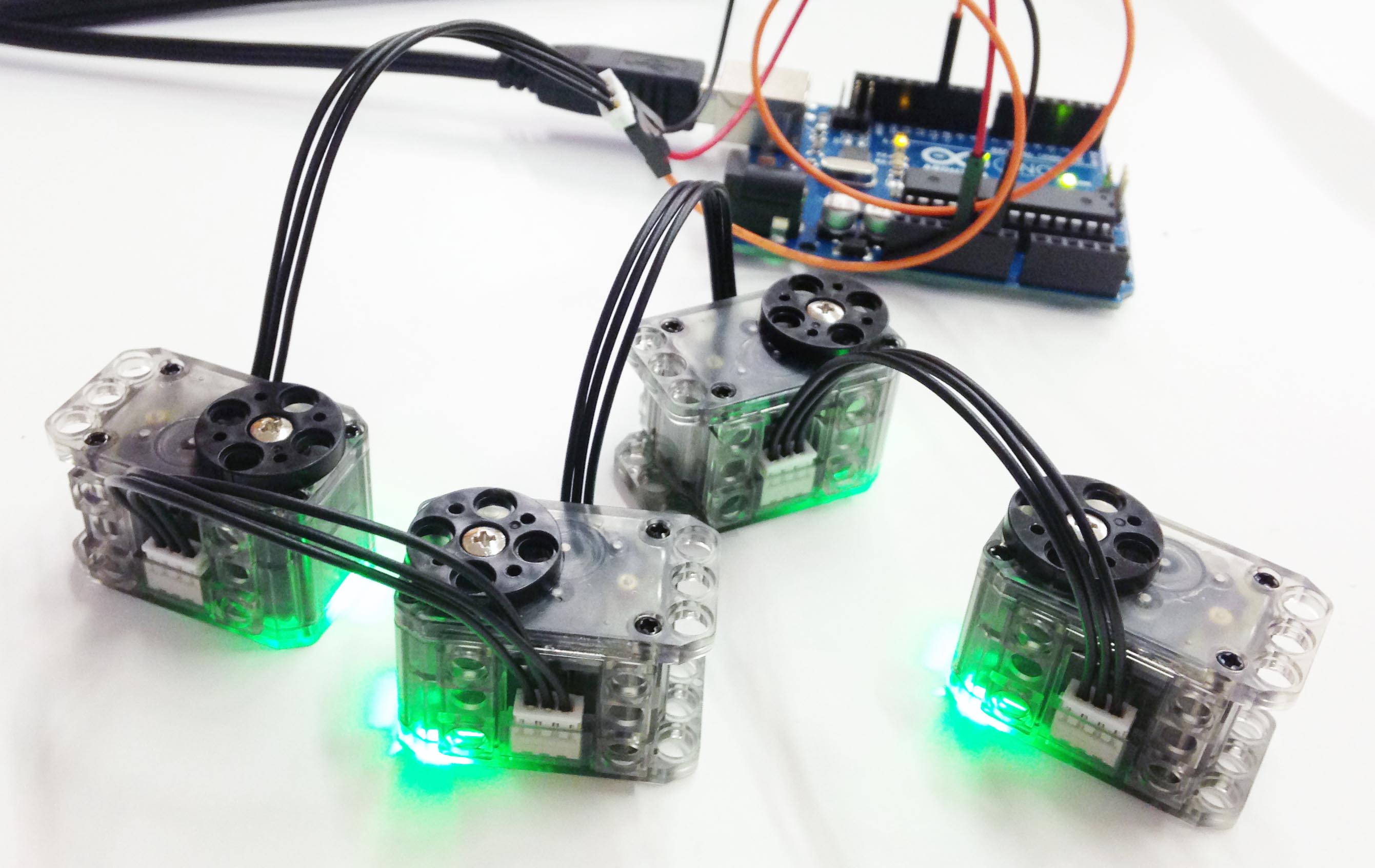 Image credit: Hackerspace Adelaide
I was able to find three different approaches on the internet: communicating using only software, and no additional hardware; using a tri-state buffer IC; and using a simple passive transistor circuit. I did not find success in these approaches, though I believe they can work in theory (I just couldn't do it). My approach falls into the first category of using no additional hardware, and fails to receive communication from the XL320, though it can send it.
Other Approach 1: No Extra Circuitry
This approach comes from Hackerspace Adelaide on Github. It implements a software-only attempt for sending to and receiving from the XL320, by simply wiring the TX and RX pins on the Arduino both to the XL320's data pin. I was able to use it to send some commands to the XL320 successfully (LED blink). However, it doesn't work for all commands to the XL320, and I was not able to use it to receive feedback from the XL320; I think this part is not yet implemented.
Overall, it serves as good skeleton code for sending commands to the XL320, and should work with a few fixes. However, I am not sure that the approach for receiving messages from the servo without any extra circuitry is sound; I have not seen it successfully implemented.
Other Approach 2: Tri-State Buffer
This comes from Savage Electronics, and uses a tri-state buffer - 74LS241 (below image) to manage the communication with the XL320. The tri-state buffer allows a data input to change whether certain channels are turned off or on. If we wire the RX and TX pins of the Arduino to different channels on the buffer, and then wire the data pin on the XL320 to both channels, then we can use this data input on the buffer to turn only the TX channel on when we are transmitting to the servo, and to turn only the RX channel on at all other times. This should allow us to have full communication with the XL320.
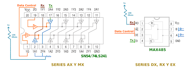 Image credit: Savage Electronics
However, there are a few issues with this implementation: firstly, it is written for the Dynamixel AX12. This is a different servo that uses a different protocol, so the libraries in the implementation from Savage Electronics need a deep rewrite to work with the XL320. Secondly, from my inspection of the code, the logic controlling the tri-state buffer is not 100% correct. It may be due to the differences in communication protocols between the two servos, but I think that it needs editing beyond this. And thirdly, there is a potential issue with the timing/latency of the data control: the XL320 has an adjustable response delay before returning its response to a command ("Return Delay Time"), with a maximum value of 0.508 ms, and a default value of 0.5ms. The default value should be fine, but if it is set too low, then the Arduino might not be able to switch the tri-state buffer in time to receive the return message from the XL320.
Other Approach 3: Passive Transistor Circuit
This third approach comes from Nerd Ralph, and uses a passive and minimal single-transistor circuit to control communication with a half-duplex serial device. It works by cutting off the Arduino TX port when the half-duplex device (the XL320) is transmitting, and cutting off the Arduino RX port when the TX is transmitting a 0, and "idling" the circuit when the TX is transmitting a 1.
I tested the logic table that Nerd Ralph described in his blog post (just using a multimeter), and found that it was correct. However, I am not sure that this will translate to successful communication with the XL320. I know it will work for transmitting to the XL320, but I am concerned that the XL320's transmissions will not make it through the transistor if the TX voltage is not actively controlled high, and I am not sure how to actively bring the TX voltage high throughout the transmission process.
Other Approach 4: Using Robotis's Special Microcontroller
This approach uses the OpenCM9.04 Microcontroller from Robotis (below), which is specially designed to interface with the XL320. In conjunction with the free and openly available OpenCM IDE, which is a slightly modified version of the Arduino IDE, it is supposed to provide easy libraries and example code to use the full functionality of the XL320. However, both the microcontroller and the code are not fully functional.
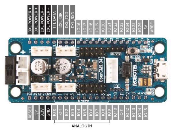 Image credit: Banana Robotics
There were numerous problems with the microcontroller, including intermittent communication failures that seemed to be due to poor grounding on the controller, and poorly made electrical connections. Futher, the board is counterintuitively built to only accept power from two 3.7V batteries; the two power sockets must be connected in series to work with a normal 7.4V battery or other DC voltage source. But the most disappointing failure was in the libraries and software from Robotis: even using their unedited example code with their microcontroller and verified working components and connections, I was unable to receive messages back from the XL320. There was simply no response returned. It is definitely not worth purchasing this board for it only to function partially, and poorly at that!
My Approach
Essentially, I simply hard-coded the communication protocol, in an effort to understand it and verify it. This is not very practically useful, but it is the only thing that I was able to make work consistently. This sounds like it would be really easy, but the documentation on the XL320 is not great, and that made it a lot harder - I'll summarize some annotations on the documentation at the bottom of the post. Here's what I did:
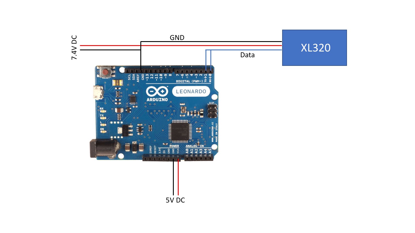 Wiring for connecting XL320 to Arduino
I connected the XL320 to the Arduino by simply wiring the data pin from the servo into both the TX and RX ports. I suppose the RX port is irrelevant, because I never was able to use it, but it can't hurt. Connect the XL320 and Arduino to power, and make sure the grounds are wired together.
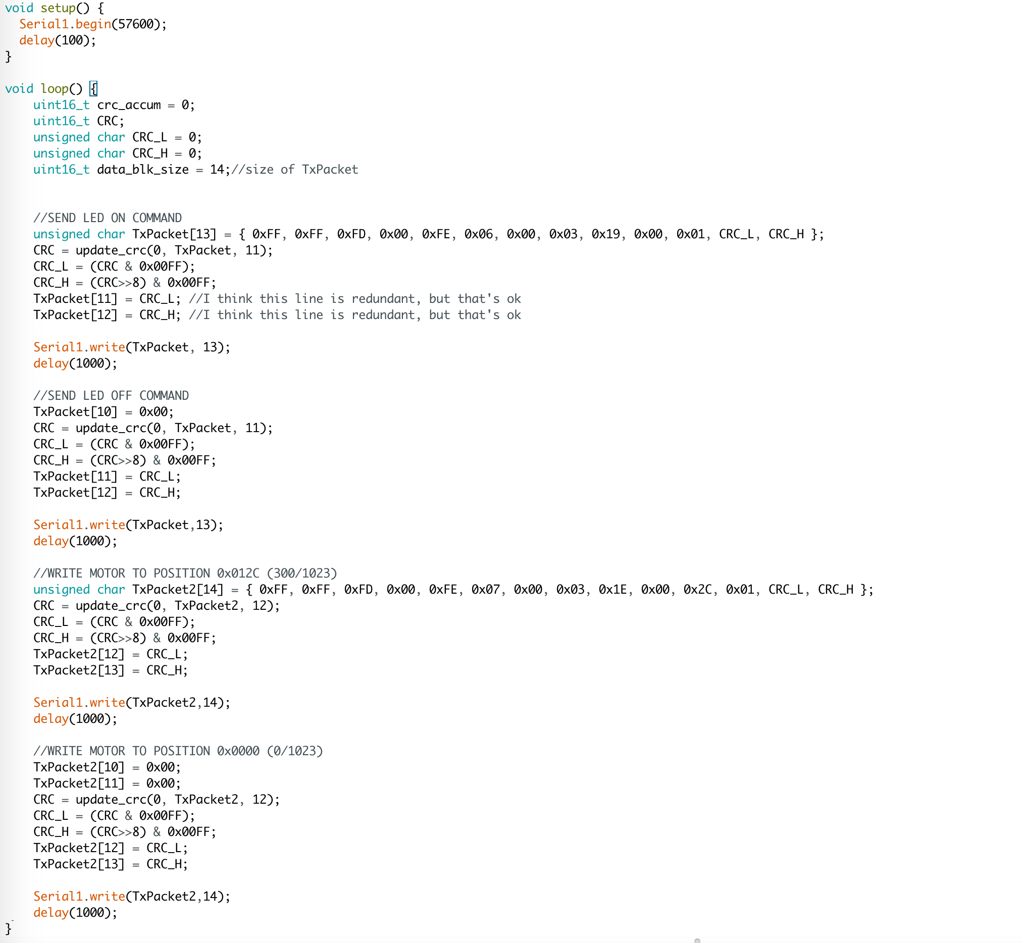
The below code turns the LED on the motor ON for one second, then turns it OFF, then writes the motor to about a third of its total range, waits a second, and then writes the motor back to 0. I hard-coded the serial messages so as to better understand them.
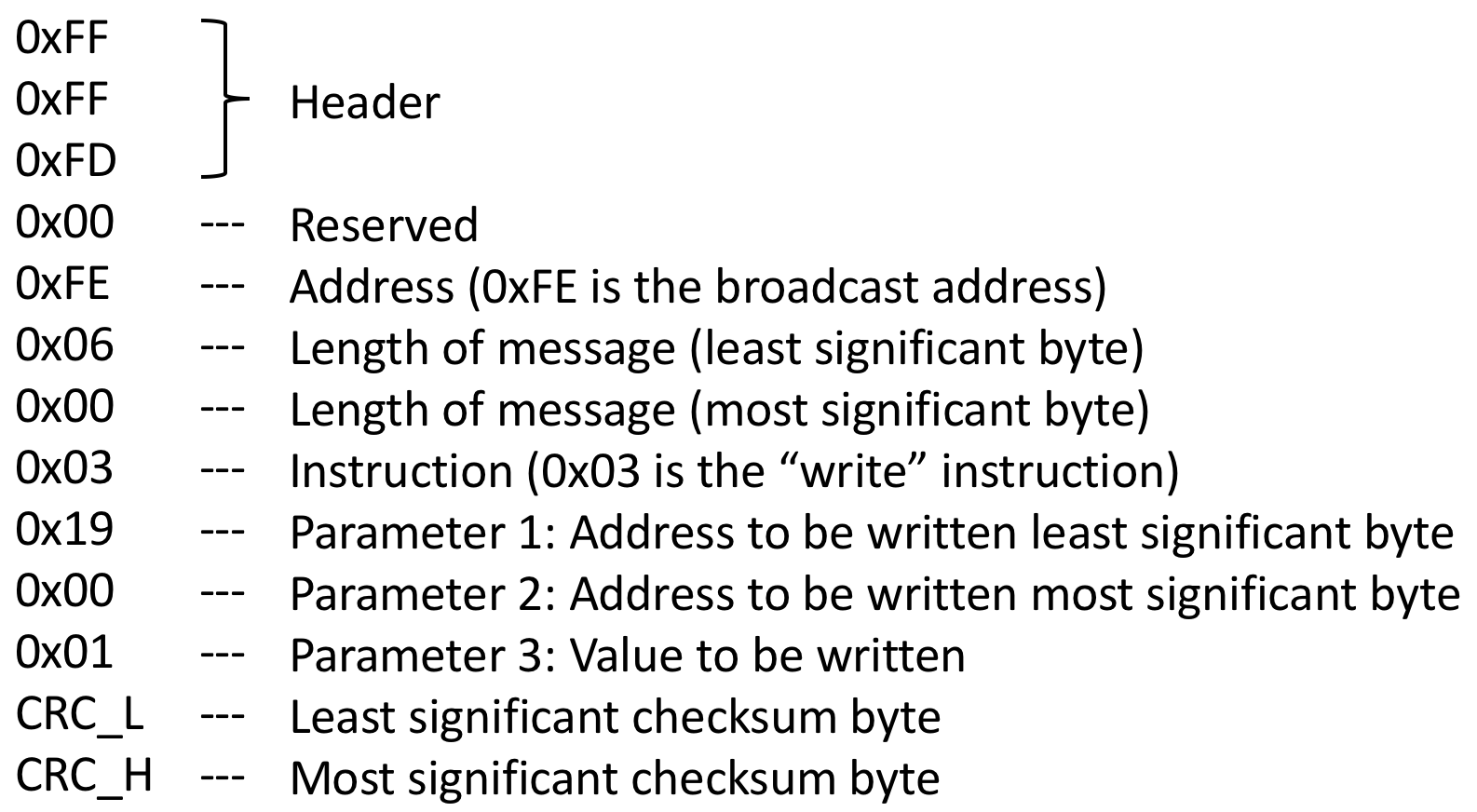
Below is one of the serial messages, unpacked. The three-byte header is always the same, as is the reserved 0x00. The address is the address of the motor that the instruction is intended for, but if you're only using one motor, you can just use the broadcast address, 0xFE. The next two bytes are the length of the packet after the length bytes, so the number of parameters plus 3. Then is the instruction byte, followed by the parameters of the instruction. Finally, the last two bytes are the checksum, which is calculated using the update_crc function from Robotis.
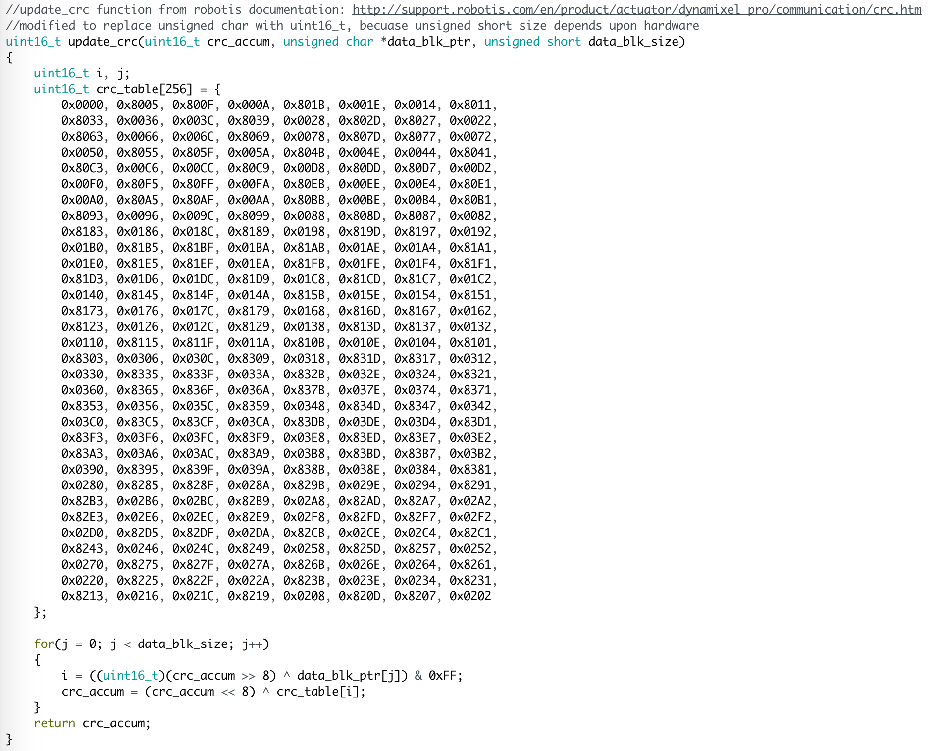
Below is the update_crc function from Robotis, available here. However, I modified it slightly; it doesn't work on all computers/microcontrollers in the published state. I simply changed unsigned short variables to uint16_t, so that they would have the same size regardless of hardware.
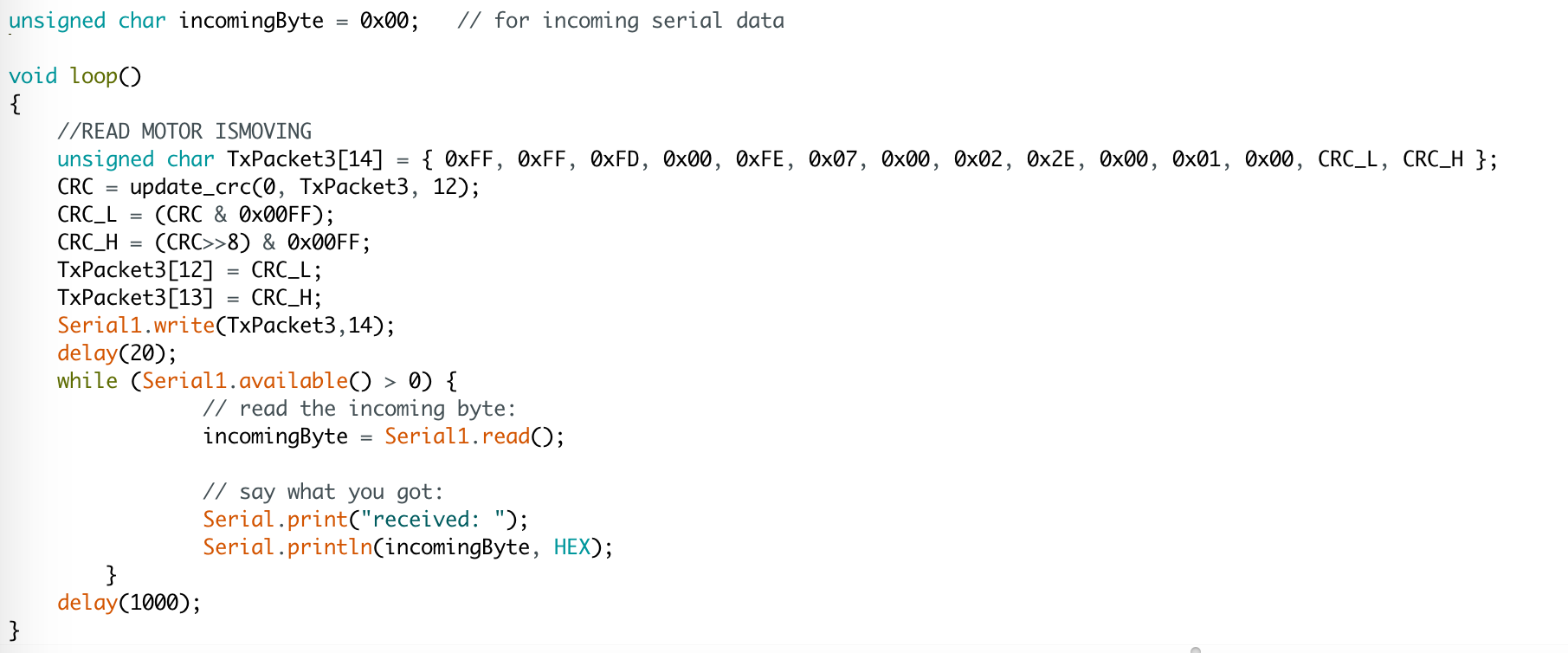
Finally, below is code that sends the motor a command to read the IS_MOVING byte, and then listens for the response. I was not able to get this to work with my hardware setup; the motor simply didn't send anything back. However, based at least on the libraries from Robotis, this is the correct command to request a response.
Here is all of the code above, compiled together into one arduino file that is copy-pastable.
Useful Resources
- XL320 Documentation
- Dynamixel 2.0 Protocol (the one used by XL320) Documentation
- Ardyno Library - another library that claims to do it all through software, but which I had no success with
Notes on XL320 and Dynamixel 2.0 Protocol Documentation
- On the XL320 control table in the XL320 documentation, the addresses of data in the XL320 memory are listed as "Address (Hexadecimal)". However, they are really in base 10! So the LED Byte, with address 25 in base 10, is really at address
0x19. - It is specified above, but I want to reiterate that individual components of the packets are little-endian. This means that the least significant bit of an address or multi-byte value will come first (left).
- The number of parameters for a write command depends upon the size value specified in the control table. If you are writing the value of the LED, for example, which is only one byte, then there will be three parameters in the packet: address LSB, address MSB, and value. If you are writing Goal Position, which is two bytes, then there will be four parameters: address LSB, address MSB, value LSB, value MSB.